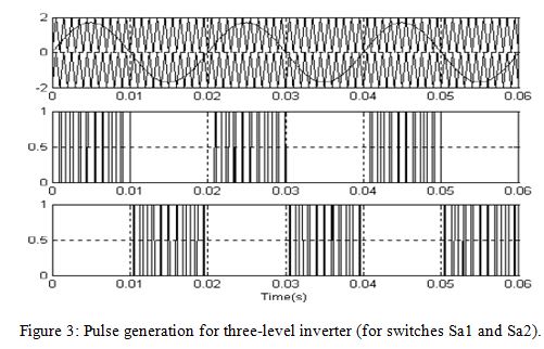
Seventeen-Level Inverter
Formed by Cascading
Flying Capacitor and Floating
Capacitor H-Bridges
ABSTRACT:
A multilevel inverter for generating 17 voltage
levels using a three-level flying capacitor inverter and cascaded H-bridge modules
with floating capacitors has been proposed. Various aspects of the proposed
inverter like capacitor voltage balancing have been presented in the present
paper. Experimental results are presented to study the performance of the
proposed converter. The stability of the capacitor balancing algorithm has been
verified both during transients and steady state operation. All the capacitors in
this circuit can be balanced instantaneously by using one of the pole voltage
combinations. Another advantage of this topology is its ability to generate all
the voltages from a single dc-link power supply which enables back-to-back
operation of converter. Also, the proposed inverter can be operated at all load
power factors and modulation indices. Additional advantage is, if one of the H-bridges
fail, the inverter can still be operated at full load with reduced number of
levels. This configuration has very low dv/dt and common-mode voltage
variation.
KEYWORDS:
1.
Cascaded
H-bridge
2.
Flying
capacitor
3.
Multilevel
inverter
4.
17-level
inverter.
SOFTWARE: MATLAB/SIMULINK
CIRCUIT DIAGRAM:


CONCLUSION:
A
new 17-level inverter configuration formed by cascading a three-level flying
capacitor and three floating capacitor Hbridges has been proposed for the first
time. The voltages of each of the capacitors are controlled instantaneously in
few switching cycles at all loads and power factors obtaining high performance output
voltages and currents. The proposed configuration uses a single dc link and
derives the other voltage levels from it. This enables back-to-back converter
operation where power can be drawn and supplied to the grid at prescribed power
factor. Also, the proposed 17-level inverter has improved reliability. In case of
failure of one of the H-bridges, the inverter can still be operated with
reduced number of levels supplying full power to the load. This feature enables
it to be used in critical applications like marine propulsion and traction
where reliability is of highest concern. Another advantage of the proposed
configuration is modularity and symmetry in structure which enables the
inverter to be extended to more number of phases like five-phase and six-phase
configurations with the same control scheme. The proposed inverter is analyzed
and its performance is experimentally verified for various modulation indices
and load currents by running a three-phase 3-kW squirrel cage induction motor.
The stability of the capacitor balancing algorithm has been tested experimentally
by suddenly accelerating the motor at no load and observing the capacitor
voltages at various load currents.
REFERENCES:
[1]
J. Rodriguez, J.-S. Lai, and F. Z. Peng, “Multilevel inverters: A survey of topologies,
controls, and applications,” IEEE Trans. Ind. Appl., vol. 49, no. 4, pp.
724–738, Aug. 2002.
[2]
L. G. Franquelo, J. Rodriguez, J. I. Leon, S. Kouro, R. Portillo, and M. A. M.
Prats, “The age of multilevel converters arrives,” IEEE Ind. Electron. Mag.,
vol. 2, no. 2, pp. 28–39, Jun. 2008.
[3]
S. Kouro, M. Malinowski, K. Gopakumar, J. Pou, L. G. Franquelo, B.Wu, J.
Rodriguez, M. A. Perez, and J. I. Leon, “Recent advances and industrial applications
of multilevel converters,” IEEE Trans. Ind. Electron., vol. 57, no. 8,
pp. 2553–2580, Aug. 2010.
[4]
A. M. Massoud, S. Ahmed, P. N. Enjeti, and B. W.Williams, “Evaluation of a
multilevel cascaded-type dynamic voltage restorer employing discontinuous space
vector modulation,” IEEE Trans. Ind. Electron., vol. 57, no. 7, pp. 2398–2410,
Jul. 2010.
[5]
S. Rivera, S. Kouro, B.Wu, S. Alepuz,M. Malinowski, P. Cortes, and J. R. Rodriguez,
“Multilevel direct power control—a generalized approach for grid-tied
multilevel converter applications,” IEEE Trans. Power Electron., vol.
29, no. 10, pp. 5592–5604, Oct. 2014.