asokatechnologies@gmail.com 09347143789/09949240245

Search This Blog

Wednesday 24 June 2015

Modeling and Simulation of All-Electric Ships With Low-Voltage DC Hybrid Power Systems

ABSTRACT:

DC hybrid power systems are of interest for future low emission, fuel-efficient vessels. In spite of the advantages they offer on board a ship, they result in a complex, interconnected system, which requires effective analysis tools to enable a full realization of the advantages. Modelling and simulation are essential tools to facilitate design, analysis, and optimization of the system. This paper reviews modelling of hybrid electric ship components including mechanical and electrical elements. Power electronic converters are modelled by non-linear averaging methods to suit system-level studies. A unified model for bidirectional converters is proposed to avoid transitions between two separate models. A simulation platform using the derived models is developed for the system-level analysis of hybrid electric ships. Simulation results of power sharing among two diesel generators, a fuel cell module, and an energy storage system are presented for three modes of operation.

KEYWORDS:
1.      DC distribution systems
2.      Modeling
3.      Simulation
4.      Transportation.

SOFTWARE: MATLAB/SIMULINK

BLOCK DIAGRAM:

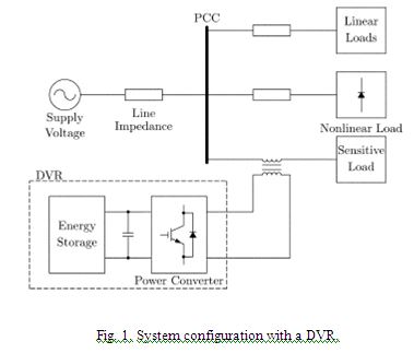
                               Fig. 1. Single-line diagram overview of a typical shipboard dc hybrid electric power system.


CONCLUSION:
Modeling of an all-electric ship with low-voltage dc power system was carried out. Averaging methods were used to model the power electronic converters by neglecting high-frequency switching behaviour inorder to reduce the computation burden and time. A simulation platform was developed using the derived models 
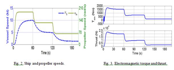
of different components for system-level studies. The simulation results for a sailing profile of an all-electric ship showed how the dynamic behaviors of different mechanical and electrical variables can be observed and studied by using the simulation program. Providing significant savings in terms of time and computational intensity, the presented simulation platform could be useful for long-term or repetitive simulations that are required for research on all-electric ship dc power systems.

REFERENCES:
[1] A. K. Adnanes, “Maritime electrical installations and diesel electric propulsion,” ABB AS Marine, Oslo, Norway, 2003.
[2] J. M. Apsley, A. Gonzalez-Villasenor, M. Barnes, A. C. Smith, S.Williamson, J. D. Schuddebeurs, P. J. Norman, C. D. Booth, G. M. Burt, and J. R. McDonald, “Propulsion drive models for full electric marine propulsion systems,” IEEE Trans. Ind. Appl., vol. 45, no. 2, pp. 676–684, Mar. 2009.
[3] S. De Breucker, E. Peeters, and J. Driesen, “Possible applications of plugin hybrid electric ships,” in Proc. IEEE Electric Ship Technol. Symp., Apr. 20–22, 2009, pp. 560–567.
[4] P. Mitra and G. K. Venayagamoorthy, “An adaptive control strategy for DSTATCOM applications in an electric ship power system,” IEEE Trans. Power Electron., vol. 25, no. 1, pp. 95–104, Jan. 2010.


An Improved Power-Quality 30-Pulse AC–DC for Varying Loads

ABSTRACT:
This paper presents the design and analysis of a novel 30-pulse ac–dc converter for harmonic mitigation under varying loads. The proposed 30-pulse ac-dc converter is based on a polygon connected autotransformer with reduced magnetic. The proposed ac–dc converter is able to eliminate lower than 29th order harmonics in the ac supply current. The resulting supply current is near sinusoidal in shape with low total harmonic distortion and a nearly unity power factor. Moreover, the design of an autotransformer is modified to make it suitable for retrofit applications, where presently a 6-pulse diode bridge rectifier is used. To validate the proposed approach, various power-quality indices are presented under varying loads. The proposed ac–dc converter is found to be suitable for retrofit applications with a large load variation and where harmonic reduction is more stringent. The laboratory prototype of the proposed autotransformer-based 30-pulse ac–dc converter is developed and test results are presented which validate the developed design procedure and the simulation models of this ac–dc converter.

KEYWORDS:
1.      Auto transformer
2.      Multipulse ac–dc converter
3.      Polygon connection
4.      Power-quality (PQ) improvement.

SOFTWARE: MATLAB/SIMULINK

CIRCUIT  DIAGRAM:


EXPECTED SIMULATION RESULTS:


CONCLUSION:
A new 30-pulse ac–dc converter-feeding varying load has been designed, modeled, simulated, and developed to demonstrate its improved performance. The proposed 30-pulse ac–dc converter consists of a reduced rating polygon-connected autotransformer for producing the desired phase shifted voltages and is suitable for retrofit applications, where presently a 6-pulse diode-bridge rectifier is used. It has resulted in the elimination of a lower than 29th harmonic in the supply current. The proposed ac–dc converter has resulted in a THD of supply current of less than 5% in a wide operating range of the load with nearly unity power factor operation. The proposed converter results in the reduction in rating of the magnetics, leading to savings in weight, size, volume, and, finally, the overall cost of the converter system. The results obtained on the developed converter configuration also validate the simulated models and the design procedure.

REFERENCES:
  [1] B. K. Bose, “Recent advances in power electronics,” IEEE Trans. Power Electron., vol. 7, no. 1, pp. 2–16, Jan. 1992.
[2] G. T. Heydt, Electric Power Quality. West LaFayette, IN: Stars in a Circle Publication, 1991.
[3] M. H. J. Bollen, Understanding Power Quality Problems: Voltage Sags and Interruptions. Piscataway, NJ: IEEE Press, 2000.
[4] A. Ghosh and G. Ledwich, “Power quality enhancement using custom power devices,” in . Norwell, MA: Kluwer, 2002.
[5] F. J. M. de Seixas and I. Barbi, “A12 kWthree-phase lowTHD rectifier with high frequency isolation and regulated dc output,” IEEE Trans. Power Electron., vol. 19, no. 2, pp. 371–377, Mar. 2004.

Monday 22 June 2015

Elimination of Harmonics in a Five-Level Diode-Clamped Multilevel Inverter Using Fundamental Modulation


ABSTRACT:

In this study, elimination of harmonics in a five level diode-clamped multilevel inverter (DCMLI) has been implemented by using fundamental modulation switching. The proposed method eliminates harmonics by generating negative harmonics with switching angles calculated for selective harmonic elimination method. In order to confirm the proposed method, first Matlab/ Simulink and PSIM simulation results are given. Then the proposed method is also validated by experiments with Opal-RT controller and a 10 kW three phase, five-level DCMLI prototype.

KEYWORDS:
1.      Fundamental switching
2.      Harmonic elimination
3.      Multilevel inverter.

SOFTWARE: MATLAB/SIMULINK

CIRCUIT  DIAGRAM:


EXPECTED SIMULATION RESULTS:


CONCLUSION:
The selected harmonic elimination is a popular issue in multilevel inverter design. The proposed selective harmonic elimination method for DCMLI has been validated in both simulation and experiment. The simulation and experimental results show that the proposed algorithm can be used to eliminate any number of specific lower order harmonics effectively and results in a dramatic decrease in the output voltage THD. In the proposed harmonic elimination method, the lower order harmonic distortion is largely reduced in fundamental switching. Furthermore, in the experiments reported here, an induction motor load is connected to the three-phase five-level DCMLI, and the current as well as the voltage waveforms are collected for analysis. The FFTs of these waveforms show that their harmonic content is close to the simulated values.

REFERENCES:
[1] J. Rodríguez, J. S. Lai, F. Z. Peng, “Multilevel inverters: a survey of topologies, controls, and applications,” IEEE Transactions on Industrial Electronics, vol.49, no.4, pp. 724-738, 2002.
[2] J. S. Lai, F. Z. Peng, “Multilevel converters-a new breed of power converters,” IEEE Transactions on Industry Applications, vol. 32, no.3, pp. 509-517, 1996.
[3] L. M. Tolbert, F. Z. Peng, T. G. Habetler, “Multilevel converters for large electric drives,” IEEE Transactions on Industry Applications, vol. 35, no. 1, pp. 36–44, Jan./Feb. 1999.
[4] S. Khomfoi, L. M. Tolbert, “Multilevel Power Converters,” Chapter 17, Power Electronics Handbook, 2nd Edition, Elsevier, ISBN 978-0- 12-088479-7, pp. 451-482, 2007.
[5] J. N. Chiasson, L. M. Tolbert, K. J. McKenzie, Z. Du, “A complete solution to the harmonic elimination problem,” IEEE Transactions on Power Electronics, vol. 19, no. 2, pp. 491-499, 2004.


Quasi Current Mode Control for the Phase-Shifted
Series Resonant Converter

ABSTRACT:

A novel indirect current mode control is applied in the phase-shifted series resonant converter system. The current is generated from resonant tank vector and the resonant current is regulated indirectly through quasi current mode control and thus the dynamic performance of the converter system is improved. Only single voltage feedback is required for the system. The proposed system consists of two control loops with one inner resonant vector and one outer voltage loop. Analysis and practical experiments are carried out and the results show the better performance compared with that of the conventional control.

KEYWORDS:
1.      Dynamic performance
2.      Dynamic response
3.      Phase shifted series resonant converter (PSRC)
4.       Quasi current mode control.

SOFTWARE: MATLAB/SIMULINK


CIRCUIT DIAGRAM:


BLOCK DIAGRAM:


EXPECTED SIMULATION RESULTS:


CONCLUSION:
The proposed control method based on the indirectly regulation of the resonant current is applied to the phase-shifted resonant converter. Only single voltage feedback is needed and it is converted to resonant tank vector components. Thus the output voltage is controlled more effectively and the dynamic performance is improved. Better performance has been verified through system analysis and experiments. In addition, the construction of the reformed control system is simple because only single voltage sensor is required. No current sensor is needed and the reformed control is monitored internally through quasi current vector.

REFERENCES:
[1] D. M. Sable and F. C. Lee, “The operation of a full bridge, zero voltage switched PWM converter,” in Proc. Virginia Power Electron. Ctr. Sem., 1989, pp. 92–97.
[2] A. J. Forsyth, P. D. Evans, M. R. D. Al-Mothafar, and K. W. E. Cheng, “A comparison of phase-shift controlled resonant and square-wave converters for high power ion engine control,” in Proc. Eur. Space Power Conf., 1991, pp. 179–185.
[3] H. L. Chan, K. W. E. Cheng, and D. Sutanto, “Phase-shift controlled DC-DC converter with bi-directional power flow,” Proc. Inst. Elect. Eng., vol. 148, no. 2, pp. 193–201, Mar. 2001.
[4] A. J. Forsyth, P. D. Evans, K. W. E. Cheng, and M. R. D. Al-Mothafar, “Operating limits of power converters for high power ion engine control,” in Proc. 22nd Int. Elect. Propul. Conf., 1991, [CD ROM].
[5] R. L. Steigerwald, “A comparison of half-bridge resonant converter topologies,” IEEE Trans. Power Electron., vol. PE-3, no. 2, pp. 174–182, Apr. 1988.

System Simulation of 3-phase PWM Rectifier Based on Novel Voltage Space Vector

ABSTRACT:

A novel voltage space vector control method based on Hysteresis Current Control is proposed. This method gives the optimal space vector by detecting the current error space vector and the system reference voltage space vector, and then controls the current error below the hysteresis width. Voltage space vector is introduced into the control system to eliminate the phase interference, and it can be realized simply without complicated vector transform. The proposed method has fast current response, and can limit the current error and the switching frequency with good current tracking performance. The system Mathematical mode is set up in this paper. The validity of the mathematical model and its control method are confirmed by MAT-LAB/SIMULINK simulation.

SOFTWARE: MATLAB/SIMULINK
  

BLOCK DIAGRAM:

EXPECTED SIMULATION RESULTS:


CONCLUSION:
In this paper a novel SVM-Based Hysteresis Current Control for 3-phase PWM VSR is suggested, which utilizes all advantages of the HCC and SVM technique. This method gives the optimal space vector by detecting the current error space vector and the system reference voltage space vector, and then controls the current error below the hysteresis width. The method can reduce the switching frequency, and has good current tracking performance. The validity of the mathematical model and its control method are confirmed by MAT-LAB/SIMULINK simulation.

REFERENCES:
[1] J. W. Dixon and B. T. Ooi, “Indirect current control of unity power factor sinusoidal current boost type three-phase rectifier,” IEEE Transactions on Industrial Electronics, vol. 35, no. 4, pp. 508-515, Nov. 1988.
[2] M. P. Kazmierkowski and L. Malesani, “Current control techniques for three-phase voltage-source PWM converters: A Surrey,” IEEE Transactions on Industrial Electronics, vol. 45, no. 5, pp. 691-703, Oct. 1998.
[3] B. T. Ooi, J. C. Salmon, J. W. Dixon, and A. B. Kulkarni, “A three phase controlled current PWM convert with leading power factor,” IEEE Transactions on Industry Applications, vol. IA-23, no. 1, pp. 78-84, 1987.
[4] R. Wu, S. B. Dewan, and G. R. Slemon, “PWM AC-to-DC converter with fixed switching frequency,” IEEE Transactions on Industry Applications, vol. 26, no. 5, pp. 880-885, Sep-Oct, 1990.
[5] T. G. Habetler, “A space vecter-based rectifier regulator for AC/DC/AC converters,” IEEE Transactions on Power Electronics, vol. 8, no. 1, pp. 30-36, Jan. 1993.
Improving the Dynamic Performance of Wind
Farms with STATCOM

ABSTRACT:

When integrated to the power system, large wind farms can pose voltage control issues among other problems. A thorough study is needed to identify the potential problems and to develop measures to mitigate them. Although integration of high levels of wind power into an existing transmission system does not require a major redesign, it necessitates additional control and compensating equipment to enable (fast) recovery from severe system disturbances. The use of a Static Synchronous Compensator (STATCOM) near a wind farm is investigated for the purpose of stabilizing the grid voltage after grid-side disturbance such as a three phase short circuit fault. The strategy focuses on a fundamental grid operational requirement to maintain proper voltages at the point of common coupling by regulating the voltage. The DC voltage at individual wind turbine (WT) inverters is also stabilized to facilitate continuous operation of wind turbines during disturbances.

KEYWORDS:
1.      Wind turbine
2.      Doubly-fed Induction Generator
3.      STATCOM
4.      Three phase fault
5.      Reactive power support.

SOFTWARE: MATLAB/SIMULINK

BLOCK DIAGRAM:


EXPECTED SIMULATION RESULTS:


CONCLUSION:
Wind turbines have to be able to ride through a fault without disconnecting from the grid. When a wind farm is connected to a weak power grid, it is necessary to provide efficient power control during normal operating conditions and enhanced support during and after faults. This paper explored the possibility of connecting a STATCOM to the wind power system in order to provide efficient control. An appropriately sized STATCOM can provide the necessary reactive power compensation when connected to a weak grid. Also, a higher rating STATCOM can be used for efficient voltage control and improved reliability in grid connected wind farm but economics limit its rating. Simulation studies have shown that the additional voltage/var support provided by an external device such as a STATCOM can significantly improve the wind turbine’s fault recovery by more quickly restoring voltage characteristics. The extent to which a STATCOM can provide support depends on its rating. The higher the rating, the more support provided. The interconnection of wind farms to weak grids also influences the safety of wind turbine generators. Some of the challenges faced by wind turbines connected to weak grids are an increased number and frequency of faults, grid abnormalities, and voltage and frequency fluctuations that can trip relays and cause generator heating.

REFERENCES:
[2] T. Sun, Z. Chen, F. Blaabjerg, “Voltage recovery of grid-connected wind turbines with DFIG after a short-circuit fault,” 2004 IEEE 35th Annual Power Electronics Specialists Conf., vol. 3, pp. 1991-97, 20-25 June 2004.
[3] E. Muljadi, C.P. Butterfield, “Wind Farm Power System Model Development,” World Renewable Energy Congress VIII, Colorado, Aug- Sept 2004.
[4] S.M. Muyeen, M.A. Mannan, M.H. Ali, R. Takahashi, T. Murata, J. Tamura, “Stabilization of Grid Connected Wind Generator by STATCOM,” IEEE Power Electronics and Drives Systems Conf., Vol. 2, 28-01 Nov. 2005.
[5] Z. Saad-Saoud, M.L. Lisboa, J.B. Ekanayake, N. Jenkins, G. Strbac, “Application of STATCOMs to wind farms,” IEE Proceedings – Generation, Transmission, Distribution, vol. 145, pp.1584-89, Sept 1998.


Saturday 20 June 2015

A Versatile Control Scheme for a Dynamic Voltage
Restorer for Power-Quality Improvement

ABSTRACT:

This paper presents a control system based on a repetitive controller to compensate for key power-quality disturbances, namely voltage sags, harmonic voltages, and voltage imbalances, using a dynamic voltage restorer (DVR). The control scheme deals with all three disturbances simultaneously within a bandwidth. The control structure is quite simple and yet very robust; it contains a feed forward term to improve the transient response and a feedback term to enable zero error in steady state. The well-developed graphical facilities available in PSCAD/EMTDC are used to carry out all modeling aspects of the repetitive controller and test system. Simulation results show that the control approach performs very effectively and yields excellent voltage regulation.

KEYWORDS:
1.      Dynamic voltage restorer (DVR)
2.      Harmonic distortion
3.      Power quality (PQ)
4.      Repetitive control
5.      Voltage sag.

SOFTWARE: MATLAB/SIMULINK


BLOCK DIAGRAM:

EXPECTED SIMULATION RESULTS:


CONCLUSION:
The use of dynamic voltage restorers in PQ-related applications is increasing. The most popular application has been on voltage sags amelioration but other voltage-quality phenomena may also benefit from its use, provided that more robust control schemes than the basic PI controller become available. A case in point is the so called repetitive controller proposed in this paper, which has a fast transient response and ensures zero error in steady state for any sinusoidal reference input and for any sinusoidal disturbance whose frequencies are an integer multiple of the fundamental frequency. To achieve this, the controller has been provided with a feed forward term and feedback term. The design has been carried out by studying the stability of the closed loop system including possible modeling errors, resulting in a controller which possesses very good transient and steady-state performances for various kinds of disturbances. A key feature of this control scheme is its simplicity; only one controller is required to eliminate three PQ disturbances, namely, voltage sags, harmonic voltages, and voltage imbalances. The controller can be implemented by using either a stationary reference frame or a rotating reference frame. In this paper, the highly developed graphical facilities available in PSCAD/EMTDC have been used very effectively to carry out all aspects of the system implementation. Comprehensive simulation results using a simple but realistic test system show that the repetitive controller and the DVR yield excellent voltage regulation, thus screening a sensitive load point from upstream PQ disturbances.

REFERENCES:
[1] M. H. J. Bollen, “What is power quality?,” Elect. Power Syst. Res., vol. 66, no. 1, pp. 5–14, July 2003.
[2] J. G. Nielsen and F. Blaabjerg, “A detailed comparison of system topologies for dynamic voltage restorers,” IEEE Trans. Ind. Appl., vol. 41, no. 5, pp. 1272–1280, Sep./Oct. 2005.
[3] V. K. Ramachandaramurthy, A. Arulampalam, C. Fitzer, C. Zhan, M. Barnes, and N. Jenkins, “Supervisory control of dynamic voltage restorers,” Proc. Inst. Elect. Eng., Gen., Transm. Distrib, vol. 151, no. 4, pp. 509–516, Jul. 2004.
[4] P. T. Nguyen and T. K. Saha, “Dynamic voltage restorer against balanced and unbalanced voltage sags: Modelling and simulation,” in Proc. IEEE Power Eng. Soc. General Meeting, Jun. 2004, vol. 1, pp. 639–644, IEEE.
[5] M. H. J. Bollen, Understanding Power Quality Problems: Voltage Sags and Interruptions.. Piscataway, NJ: IEEE Press, 2000.